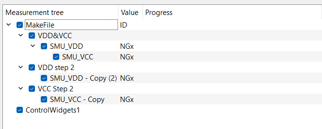
As I was understanding this layout will now uncomnfigure SMU_VDD and SMU_VCC after entering the second step? Is it possible to prevent this, since we have complex multistep bootup sequences we have to use. In this cas we sweep VCC and VDD in parallel to a Voltage than have to rais VDD as first further and after that the VCC further.
Will this work or is this impossible to do at the moment?
Thanks for your help
Marc
It is correct that a module and the related instrument is unconfigured when a module is no more in an active branch. This means indeed that SMU_VDD and SMU_VCC get unconfigured once SweepMe! goes from branch 1 to branch 2.
So with multiple branches it is not possible right now. We have an idea in mind that instruments are not unconfigured if the same combination of a driver, a port, and a channel (if available) is used in a next branch. In this case, it is obvious that an instrument is still being used further. There is still some conceptional work to do as the instrument would still be configured again which should not interfere with the state that the instrument has.
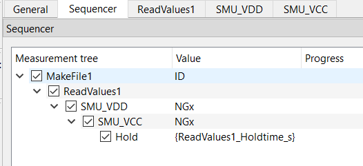
The best solution that I can offer right now is to keep all SMUs in one branch and use the ReadValues module to create a recipe for bootup and parallel measurement.
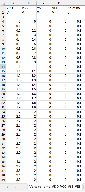
Now you create a Excel of csv file that is loaded by the ReadValues module. There you define columns for voltage VCC, voltage VDD and an optional hold time.
The voltages can forwarded to the SMU modules via selection in the Sweep value field and the Hold time can be forwarded to the Hold module using the paramete syntax with curly brackets (see widget ‘Parameters’).
You are then free to create any voltage variation you like including different time steps per voltage. The concept can be extended to further instruments.
thanks for your reply, how would you create than the csv files for such a scenario:
Ramp VDD and VCC simultaneously from 0 V to +2 V
Ramp VDD from +2 V to +3.5 V
Ramp VCC from +2 V to +6.0 V
Ramp VSS from 0 V to -3.5 V
Ramp VEE from 0 V to -2.5 V
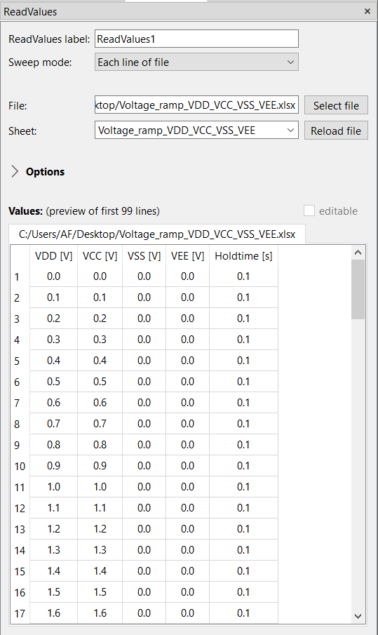
The Sweep mode of ReadValues is set to “Each line of file” which is the default. It means that ReadValues will sweep through the rows and for each line of the file the values will be handed over to the SMUs and a measurement is triggered.
This gives you a lot of freedom to create any rampup procedure. However, all data will be in one file and also the plot will show the ramp up in one line.
You can use the slicing feature in the plot to only show e.g. the last x variations of ReadValues by entering [-x:] to plot a certain part of the variation without the rest.
Thanks Axel,
then I have understand your suggestion right. I have now created an script for generating the csv file already. Looks like your approach. I will have to test this but could workout indeed.
Marc
The next step would than be, that we want to use another device after the boot up to do measurements how can this be done than without turning the SMUs off?
To be more precise: measuring current of all SMUs all one by one. How can we even only measure voltage or current without changing the device current settings?
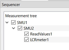
So far ReadValues was above the SMU modules, which is most intuitively, but it also works other way around.
The first branch consisting of SMU1, SMU2, ReadValues1 still works the same way. SMU1 and SMU2 do not perform an own variation. ReadValues will create the variation and at each step the values are handed over to the SMU modules, so they still get new set values that are applied.
Further at each iteration of ReadValues, all modules in the active branch are measured.
It means there is some flexibility in creating the sequence, especially if only one module makes a variation. In case multiple modules create a variation, there order is more important.
Once the sweep of ReadValues is finished, the first branch ends and SweepMe! goes into the second branch. SMU1 and SMU2 are still in an active branch, so they are not unconfigured or configured again. They remain at their set points, but now the LCRmeter as an example can perform a single measurement or a sweep.
Because SMU1, SMU2 and LCRmeter1 are in the second branch, the will be measured at each variation in this branch.
Just measuring current or voltage is not that easy because the driver always returns both as a convenience thing at each measurement point.
Hi Axel,
where can I see the implementation of the SMU module for the measurement part. I had the idea to code a new device class which could support multiple individual measurements and also could prevent a unconfigure to let the device open. I did not find any information in the code or the documentation how the measurement methods are accessed. This would also be of interest for other drivers, since if I use a Spektrum analyzer I don’t want to measure everything every time, rather I would say only to make a specific measurement.
How could this be possible or is this not possible due to programming restictions of the sweepme environment currently?
Greetings Marc
There, you can find commands that can be implenmented in a driver. They are the same for SMU, Spectrum analyzer, and other instrument modules. Some modules support extra functions that are often related to additional features of the modules that are documented in the Wiki article of each module. For example, the WaferProber module supports additional functions to load/unload a wafer outside of a measurement or can update/synchronize the wafer map.
Can I add more GUI parameters in my SMU subclass? I wanted to use this to dynamically manipulate/override the measurement function in the device class to trigger specific measurements or should this be done different?
I tried this:
 gui_parameter = {

            "SweepMode": ["Voltage in V", "Voltage in V (with wait)", "Current in A", "Current in A (with wait)"],

            "Channel": [1, 2],

            "RouteOut": ["Front"],

            "Compliance": 5.0,

            "Range": ["Auto", "10 µA", "1 mA", "10 mA", "100 mA", "3 A", "10 A"],

            "RangeVoltage": ["Auto", "20 V", "6 V"],

            "Speed": ["Fast", "Medium", "Slow"],

            "MeasurementType": ["None", "Current", "Voltage"]

            # "4wire": False,

        }
Here I wanted to add a measurement Type parameter but this does not change the gui. I think this is limited in the SMU class itself then?
Greetings
Marc
thanks for the further questions. If you like you can also create new topic/issues in the forum as this will make it easier for other users to find answers to similar questions.
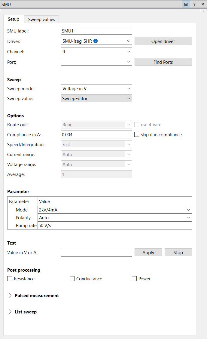
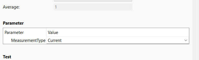
In one of the last updates of SweepMe! / the SMU module, we added a “Parameter box” to the module. Now, GUI keys that are not supported by the SMU module via the fixed GUI fields, will be shown in an additional box (similar to Logger or Switch).
Hi Axel,
if I get another topic I will make a new one.
So I updated to 1.5.7.9 and to SMU 01_12 Version. I don’t see a parameter box in the gui.
Do I have to add the parameters through another function else than
def set_GUIparameter(self):
gui_parameter = {
“MeasurementType”: [“None”, “Current”, “Voltage”]
}
Because I don’t get the Parameter box.
Thanks
Marc
They are replacing get_GUIparameter and set_GUIparameter and have the advantage that you can dynamically add and create further keys depending on the user selection.