I am running a Keithley 2602B SMU with sweepme using both channels. Channel B is used for supplying an OLED and Channel A to read photocurrent of an photodiode.
When the OLED is supplied with a regular sweep, i.e start from 0V until say 3V with steps of 0.05V, I have no problem recording the photocurrent from channel A.
However, when the OLED is run with pulsed mode, the photocurrent from channel A is orders of magnitude smaller. This leads me to believe that the photocurrent is measured either during the rise or fall period of the OLED driving pulse. I am not sure if this is the case, but in any case I was not able to solve it by tuning the “width in s”, “off time in s” or applying a delay/hold between the two actions within the sequencer.
Is there a way to synchronize the two channels in SweepMe such that the channel B can be driven in pulsed mode, with the channel A taking a measurement at a given defined point of each pulse?
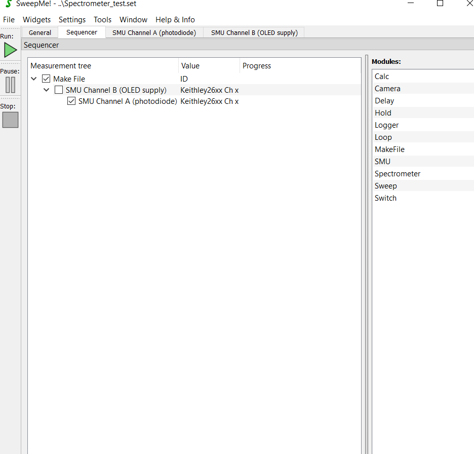
Screenshot of the sequencer (without any delay/hold modules inserted)
I have used pulse mode of the Keithley 2600 dual channel SMUs myself and I think it is as you expect. Reading the photodiode in DC mode is not in sync with the pulse. This could be also because the SMU integrates in DC mode over some time and the pulse makes only a port of this integration time. But of course only Keithley can answer this fully.
My recommendation would be to put both channels into pulse mode. The driver is written in a way that both channels then perform a synchronized Dual pulse measurement. The pulses are then fired at the same time and one of the channels encapsulates the other one but I’m not sure anymore in which direction this works.
If your photodiode is fast enough which is typically the case at e.g. 0V, you should be able to measure the correct current, while pulsing the OLED.
Apologies somehow I thought a response in this forum would be indicated in my email and i have therefore missed this completely. I am currently not able to test further, but I actually tried to run both channels in pulse mode. This however crashed the SMU with some specific error code. I do not remember which it was but over the weekend I am able to do further testing and update you then.
Hi Aron,
maybe you can check your personal notification settings, but you a right: Typically, there should be an email when there is activity in a thread you created or that you are watching.
If there is an error code, you could also test to swap channels as maybe only one is able to encapsulate the other one.
I have not used the code for a while, but it was already applied for double-channel pulse measurements once, e.g. in this publications for testing transistors at higher currents: https://www.nature.com/articles/srep44713
Now I received an email, do not know what happenend with the first reply.
I briefly read the main.py and judging from the “master” and “slave” port commands, I believe something what you suggest will be able to fix these issues. The crucial thing now is the knowledge that it is atleast possible, that is all I needed.
I will however update during the next week whether I get it working or run into some additional issues. Thank you!
The error code in dual pulse mode is fixed (i was driving the pulses with different on/off times and that probably caused the synchronization to fault).
However, with dual-pulsed mode, it seems the channel B doesnt actually measure during each channel A pulse. It takes a single measurement in the beginning and the current value does not during the whole sweep (it should atleast fluctuate around the dark current value, not stay exactly constant). It does fluctuate around the dark current when driven in non-pulsed mode.
I tested with various pulse times, up to 500 ms for both on/off, measurement duartions from 1% to 30%, all speed times (fast,normal,slow) and setting manual current ranges. The sequencer is yet again such that the photodiode channel is nested inside of the led supply channel module. I have also tried to add delay modules between the two.
Apologies for the message-bombarding. It seems adding a non-zero end value for photodiode sweep does result in correct operation. However, now the photodiode is slightly biased, whereas unbiased would be the desired condition.
probably you need to dive a bit into the code of the driver to check whether evertyhing runs as expected. Here, I can give you some first ideas about the operation of the driver.
In dual pulse mode, the two driver instances use the possibility to “communicate” with each other. This is done via the object self.port.port_properties by updating this dictionary whether a pulse operation was requested. (Sidenote: Using self.port.port_properties is deprecated and one should use the dictionary self.device_communication that each driver can use, but the Keithley 26xx driver should still work)
If the driver instances realize that two channels (A and B) request a pulsed operation, they go into dual pulse mode, and only one driver instance triggers the dual pulse. The result is then retrieved by one driver instance and handed over to the other driver instance via self.port.bufffer variable.
Thus, using a “Delay” module has no effect on the dual pulse operation as it only add a pause between consecutive measurement points defined in the sequencer. Everything you need to check whether the channels are configured as expected and results are correct can be found in the source code of the Keithley 26xx driver
It might be that the dual pulse operations of the driver so far only covers certain configurations and must be revised to some extent for other configurations, but I would have expected that it just works.
One thing that is important is setting the compliance/protection correctly. It is used in pulse measurements to define the measurement range and should thus be the upper current limit that you expect to measure. However, if the value is too large, it might be that smaller currents are not resolved anymore.
I case of your photodiode, there might be a further problem with using a 0V on level because the off level is 0 V as well I guess. You could try to use a different off level like -1 V or change the on level to -1 V. As the photocurrent should saturate at 0V and below, it should be possible to measure the photocurrent also a slightly negative voltages and thus produce a clear voltage step between off state and on state of the pulse.