Hello Axel.
This was a good suggestion. I modified the driver accordingly and it now works flawless. I just opened a pull request for it:
The Rohde & Schwarz NGPV series of power supply is a strange beast. They are 19" rack power supplies which were available also with an additional shell as standalone devices and both versions were available without any controls for pure remote operation as well. The NGPV series is mentioned in their 1984 catalog without any “new” lables and still listed in their 2004/2005 catalogue without any discontinuation notice, so it was in production for over 20 years. It seems that it has its roots in the end of the 70s or beginning of the 80s and that it was a kind of first-contact to GPIB for R&S.
To better understand how the driver works, one needs to have a look at the frontplate of the instrument and understand how it operates:
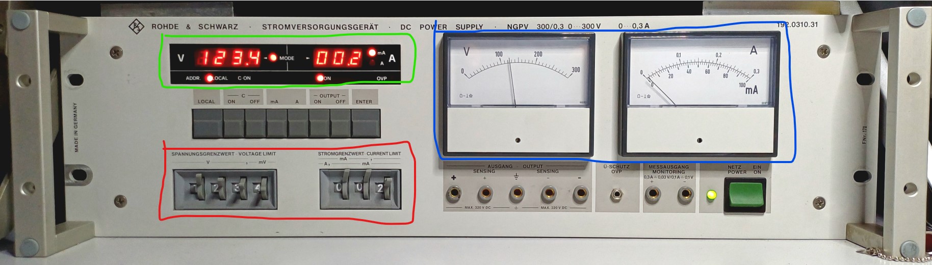
You use the levers on the rotating numerical counter within the red box to set a voltage and current compliance limit. After pressing the ENTER key, the value gets transmitted to the LED display in the green box. This is the setting that the PSU will use for its output. The actual output voltage and current gets measured/read-back via the analogue needle displays in the blue box.
It is now apparent how the unit can process input from a mechanical counter as well as digital values via GPIB: because both get transmitted to the LED display as the only source for the output values. The mechanical counter setting (red box) is not processed at any point but just when the ENTER key is pressed. After that, it remaines where it is without being reconsidered by the insturment again.
But because the instrument has two dirrefent current modes that offer different maximum values and resolutions, there is no fixed decimal point position on the mechanical counter. This gets apperent when reading the GPIB programming section of the manual: the instrument expects just a 4 digit number for voltage and a 3 digit number for current and will ignore any decimal points or commas or milliampere "m"s. Operating the instrument, you have to watch out where the decimal point is “virtually” depending on the chosen current mode.
Within the driver, the solution is to convert the given values to a numerical full-value while respecting the expected input format. For this, I implemented a nested dictionary that requires the operator to first choose which NGPV model he wants to control. When, he is offered with the choice of the available current modes per NGPV model, which link to a formating rule that is applied to the compliance input. In the same way but in a simple dictionary, the given NGPV model version is used to hand over the right formating rule for the input voltage.
There is a quirk in so far as that all models (with one exception) will stop operating if the voltage entered resembles their model ID, e.g. 300V for the NGPV. Because they could not make the mechanical counter allow 299.9V and 300.0V but not 399.9V, they just maxed out each instrument at minus one last digit, e.g. 299.9V instead of 300V. I though about creating a dictionary for the maximum values as well and to a model depended check before each applied value. But in the end, I think this would slow down the code unnesessarily as it is an easy thing to remember. Also, the instrument will set the output to 0V natively and start blinking with its display if the maximum votlage requested is above is maximum limit so no harm done here.
Best wishes,
Christian